Mark A. Dods VK3XMU (Now VK3ZR)

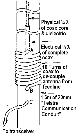
This antenna is constructed from RG58 coax and a length of 20mm “Telstra Communication Conduit”. As shown in the diagram to the right, the radiating elements are housed inside the conduit while the de-coupling coil is wound around the conduit itself.
The first antenna I made had dimensions calculated for 146.000 MHz:
- Wavelength = 300/146 = 2.054m = 2054mm
- Physical ¼ wavelength = 2054/4 = 513mm
- Electrical ¼ wavelength = 513mm x velocity factor = 0.513 x 0.66 = 339mm
These dimensions gave SWR readings from 1.5:1 at 144.000 MHz down to 1.2:1 at 147.975 MHz. Clearly the elements were too short, so I recalculated for 144 Mhz and got the following dimensions:
- Wavelength = 300/144 = 2.083m = 2083mm
- Physical ¼ wavelength = 2083/4 = 520mm
- Electrical ¼ wavelength = 520mm x velocity factor = 520 x 0.66 = 344mm
The SWR readings for this antenna are shown as #2 in the SWR table below. Finally I made a third antenna with the following dimensions:
- Core & Dielectric length: 530mm
- Complete Coax length: 351mm
The SWR readings for this antenna are shown as #3 in the SWR table below:
| f (MHz) | SWR | |
| #2 | #3 | |
| 144.000 | 1.3:1 | 1.1:1 |
| 145.000 | 1.2:1 | 1.1:1 |
| 146.000 | 1.1:1 | 1.1:1 |
| 146.250 | 1.1:1 | 1.1:1 |
| 146.500 | 1.1:1 | 1.1:1 |
| 146.750 | 1.1:1 | 1.1:1 |
| 147.000 | 1.1:1 | 1.1:1 |
| 147.975 | 1.2:1 | 1.15:1 |
Antenna #3 seems to work pretty well, so to reverse engineer it assuming a centre freq of 146.000 MHz:
- Physical ¼ wavelength
- Theoretical = 513mm
- Experimental Physical ¼ wavelength = 530mm
- Conversion factor = 530/513 = 1.03
- Electrical ¼ wavelength
- Theoretical = 339mm
- Experimental = 351mm
- Conversion factor = 351/339 = 1.04
So it looks as though our elements should be 3% – 4% longer than the theoretical lengths. Someone with more antenna theory than me may like to explain this?
Construction
- In a 1.5m length of conduit, drill three holes (marked A, B & C on diagram). A is 900mm from the top, B is 955mm from the top, and C is 985mm from the top. The holes should be just big enough to accomodate the RG58 coax.
- From a length of RG58 coax (minimum length is 2m) remove the sheath & braid to obtain the exposed physical quarter wavelength of dielectric & core.
- Mark the bottom end of the antenna (where the coil starts) with a piece of non black electrical tape.
- Attach a piece of string (approx 300mm long) to the end of the exposed dielectric.
- Insert the string into the bottom hole (C) in the conduit, feeding it towards the top of the conduit.
- Using a hook made from coat hanger or similar, hook the string out through hole B.
- Use the string to draw the coax out through hole B until you have about 1m of coax in addition to the antenna section hanging out.
- Wrap the coax ten times around the conduit and insert the string into hole A.
- Feed the antenna into hole A until the marker tape is right up to the hole.
- Starting from hole A tighten the coil around the conduit and feed any excess coax back into hole B.
- Secure the string hanging out of the top of the conduit by pulling it tight and clamping it with an end cap. (Actual Telstra conduit end caps are hard to obtain, but Clark Rubber sell a white rubber chair leg stopper that is a good tight fit over the end of the conduit.)
- Use electricians tape to weather proof the coil and associated holes in the conduit
Peter Fraser VK3ZPF has used a version of this antenna on a squid pole for SOTA work. See: http://vk3zpf.com/2012/10/spion-kopje-sota-activation.html

